

hi i made another game for domino club with freya called MEMOREL RESTORATION PROJECT. if you wanna skip the BULLSHIT and just play it its right here.
SPECIFICATIONS
Resolution: 640x352
64 HARDDRIVE BLOCKS
FRAMERATE 20Hz -> 40Hz -> 60Hz
DUE TO HARDWARE PARTICULARS, INTERFERENCE FROM RENDERING IS AUDIBLE
LANGUAGE: odin
LIBRARIES: raylib


clear_rect :: proc(x:i32, y:i32, w:i32, h:i32, color:int)
clear_screen :: proc(color:=0)
draw_image_asset :: proc(asset:[]u8, x:int, y:int, instant:bool = false)  // NB: at the developers' discretion, we can bypass any imagined hardware limitation
draw_text :: proc(text: string, bgcolor: int = 0, fgcolor: int = 15, uppercase:bool = false, newline:bool = false, fastdraw:bool = false, audio:bool = true)
draw_box :: proc(x:i32, y:i32, width:i32, height:i32, bgcolor:int, fgcolor:int, double:bool)
the way this works is all of the frame handling code is encapsulated in a function we named flip(), including rendering to the screen, waiting until the next frame (in this case at 20fps), handling input, etc.
by default, as in most games, there is a main loop that will call flip(), and run any relevant necessary code. however, at any point, you can spin up a new infinite loop and call flip() during it, essentially hijacking the main loop for as long as necessary.
here's an example for waiting for a number of frames:
waitframes :: proc (frames:int) {
    for i:int = 0; i <= frames; i+=1 {
        flip()
    }
}
or waiting for a keypress:
wait_for_input :: proc (key:rl.KeyboardKey = .KEY_NULL) {
    if key == .KEY_NULL {
        loop: for {
            if last_key_pressed != .KEY_NULL {
                last_key_pressed = .KEY_NULL
                break loop
            }
            flip()
        }
    } else {
        loop2: for {
            if key_eat(key) {
                break loop2
            }
            flip()
        }
    }
}
i had experimented a bit with this system in my game world pole stone dusk: diadem of the pole, but i only started using it partway through the project. memorel was built with it in mind for usage throughout. it is a super powerful tool that i will continue to use in future projects wherever possible. thanks
audio_write(u8(rune%256), (bgcolor * 3 + fgcolor) * 3)
audio_write :: proc(data:u8, block_size:int = AUDIO_BLOCK_SIZE) {
    if len(audio_queue) + (AUDIO_FADE * block_size) >= MAX_AUDIO_SIZE {
        return
    }
    for j :u8= 0; j < AUDIO_FADE; j += 1 {
        for i:=0; i < block_size; i+=1 { append(&audio_queue, ((data / 1) % 8 * 32) / (j + 1)) }
        for i:=0; i < block_size; i+=1 { append(&audio_queue, ((data / 8) % 8 * 32) / (j + 1)) }
        for i:=0; i < block_size; i+=1 { append(&audio_queue, ((data / 16) % 8 * 32) / (j + 1)) }
        for i:=0; i < block_size; i+=1 { append(&audio_queue, ((data / 32) % 8 * 32) / (j + 1)) }
    }
    if len(audio_queue) > MAX_AUDIO_SIZE { resize(&audio_queue, MAX_AUDIO_SIZE) }
}
audio_processor : rl.AudioCallback = proc "cdecl" (buffer:rawptr, frames:u32) {
    buffer_data :[]f32= ([^]f32)(buffer)[:frames*2]

    for i:=0; i < int(frames*2); i += 2 {
        p := (i / 2) + audio_queue_position
        if p >= len(audio_queue)-1 {
            clear(&audio_queue)
            audio_queue_position = 0
            break
        }

        if p < len(audio_queue) && i < len(buffer_data)-1 {
            buffer_data[i + 0] = (- 1.0 + f32(audio_queue[p]) / 128) * 0.2
            buffer_data[i + 1] = (- 1.0 + f32(audio_queue[p]) / 128) * 0.2
        }
    }

    if len(audio_queue) > 0 {
        audio_queue_position += int(frames) / 2
    }
}
the main concept is to write arbitrary data (roughly mapped to cover most of the possible values evenly), and any other flavor here is to fill it out more in order to make it more audible or more pleasing to listen to.
i also tweaked the "block size" in order to lower or raise the quality or bitrate of the sounds, to have something easy to tweak to change the quality of the sound until i was happy with it.
i DID try making a little music system with this but it didn't work properly so we never used it i think.

hi just a quick and small post to talk about hello welcome to my new blog! i have been porting over posts from my other blogs like off github (works with ICE btw) and medium (annoying site). i still have one more to do but im procrastinating
i've used static site generators and other blog software and i dont rly like any of it. embedding stuff was always annoying, i like writing html and i dont rly like writing markdown, and the setup was always a pain and every time i return to write a new post i have to remind myself of the entire process. annoying.
i've played with writing an entirely clientside blog thing before with javascript to show individual posts but i've been trying to even avoid javascript where it's not necessary. css and html are surprisingly powerful on their own and its kinda nice to use them instead of frameworks and whatever else.
this entire blog is just one html file (roughly 120kb so far), with a separate manually updated rss.xml alongside it. keeping it as one file means updating and modifying stuff is easy and i dont have to repeat work all over the place. it was the thing that enabled me to avoid both static site generators and also javascript
the way it works is using URI fragments (links that just have a hash target like "#hello") to individual posts,
and the css :target selector to show the correct post and hide all others. thanks to martijn frazer for the help! each post gets a permalink,
any manual process of updating is alleviated mostly by the fact i'm not writing new posts all the time, and its cute.
oh also images needed to have a loading=lazy attribute, or (only mobile??) browsers would load every
image on every post lmao.
anyway thanks for reading i just wanted to write a bit about that. low tech stuff is cool and important imo. im excited to write posts again, annoying software was a big roadblock for me and why i haven't written stuff for ages. i've had a post about the tech behind world pole stone dusk: diadem of the pole rotating for a long while

quick disclaimer before i begin, i’m gonna say a lot of only vaguely accurate stuff, to give a general idea of things instead of trying to perfectly accurately describe How Things Work. i’m not an expert in any kind of low level computer stuff, so everything is based off my vague understanding and shouldn’t be taken as The Truth entirely! to help out a bit i’m gonna put an asterisk after everything that i’m pretty sure is inaccurate. the point is to describe enough to make my point and help give all the info you need for what the article is about. thanks for understanding!!!
modern game engines are Very Good* and its very nice not to have to think about a lot of things when making games. gone are the days that you must know how to handle every aspect of how a game runs before you can even begin your new cool pong mmo*. it’s for precisely this reason i’m making my own
i’ll cover DISASTER ENGINE more in the future* but for now i’ve been dealing with one particular gripe; i’m building on top of unity for now so i can focus on the unique features of my engine before tackling the lower end of things, and for 99% of things this is working out very well*. unity is mostly just acting as a window manager, renderer and input handler while i do most of everything else in DISASTER ENGINE*. one of the driving forces behind it is exposing every piece of content the game uses, every texture, model, and script are stored externally, making every game made in the engine inherently moddable* (just start messing with the files).
there is one kind of asset, however, that unity does not let you load externally*. its shaders! (pretty sure ue4 doesn’t either*, but it looks like godot can?* i digress)
shaders are computer programs to do complex geometry and other graphical work on the graphics card, which are specialised to process that kinda stuff*, leaving the CPU to keep doing what it’s good at*. the most common cases are transforming 3d models to view space and calculating the correct texture coordinates of every pixels on screen* etc. they’re good at letting you see things*
shader languages are c-based programming languages that were created to write the programs for your gfx card to run, and they’re very powerful, and reasonably comfortable to learn*. in recent years, there’s been a rise in the creation of node based shader editors, taking advantage of the specific ways shaders work* and creating awesome easy to use and powerful interfaces for people to create Cool Shaders, without having to touch a line of code.
moving from C-style language to nodes is a very logical and powerful step*, since text-based coding is an often less-intuitive way to think about how shaders work*, while nodes actually give a much better visual representation of a lot of the processes that are happening*.
C itself also followed this trajectory, being a “human-readable” way of writing computer programs, to move away from hand-writing each specific instruction a CPU needs to do things. Writing these instructions manually is called “assembly programming” and it takes a lot more patience and logic to understand and write.* It looks like this*:

that image isn’t what cpu code actually looks like*; thats the human readable* format of it lol. in practice, this is converted to a series of bytes that the cpu traverses and interprets to execute programs.* (the middle part of the image kinda represents that)
in general the format of an assembly program is a list of instructions, each with some amount of arguments eg MOV a b (move a to b). if you aren’t familiar with these terms, its basically WHAT to do, then HOW to do it. the cpu reads the instruction, then does the thing with the parameters you give it.*
instructions tend to work on a block of memory* that is being modified and read from, to make calculations etc.*
while thinking about this, and talking about shaders with cool people on my cool discord, i had a terrible terrible idea. what if you encoded assembly instructions into an image, and wrote a shader to interpret and execute the instructions? a single shader that executes arbitrary programs, that are uploaded by providing a new texture to the shader. that sounds awful
welcome to SHAD2; shaders, but much less powerful and much more difficult. able to execute up to 256 unique instructions, with a memory of 256 floats. lets get started
to build this system i needed 3 parts: some way to write text to write the program, a system to compile an assembly-like language into a texture to send to the shader, and the shader itself, to interpret the texture as a program. obviously i could just use any text editor but for fun and aesthetics i decided to create a little IDE* to write my programs with.
to render text to the screen i used the software text rendering created here, and got to work on inputting stuff. the code is stored as a List<string>, with the intention of parsing each line as an instruction, to give a clear scope for each one. text editing is never as trivial as i remember but it didn’t take too long to get a lil thing up and running. to give an example here’s what happens when you press any character*
if (Input.anyKeyDown) {
    // when handling a keypress we first need to check for special keys
    if (Input.GetKeyDown(KeyCode.Backspace)) {
        // depending on the current line we either delete a character, or delete the empty line
        if (code[line].Length > 0) {
            code[line] = code[line].Remove(pos - 1, 1);
            pos -= 1;
        } else {
            if (line > 0) {
                line -= 1;
                pos = code[line].Length;
                code.RemoveAt(code.Count-1);
            }
        }
    } else if (Input.GetKeyDown(KeyCode.Return)) {
        // hitting return in the middle of a line should move the rest of the line to a new one
        if (pos != code[line].Length) {
            string temp = code[line];
            code[line] = code[line].Substring(0, pos);
            temp = temp.Substring(pos);
            code.Insert(line+1, temp);
        } else {
            code.Add("");
        }
        line += 1;
        pos = 0;
    } else {
        // otherwise just add the new character to the current line
        string input = Input.inputString;

        code[line] = code[line].Insert(pos, input);
        pos += input.Length;
    }
}
there’s just so many edge cases, its a bit of a grind making it feel comfortable enough to code in. but once that was up and running i could get started on the cool stuff. i added a Classic Spinning Cube to preview the eventual shader and here we are

now onto compiling. the first thing is to decide exactly what our program will look like when compiled; after some back and forth i decided to go for the simplest route of encoding each instruction into a series of pixels. each pixel would lay out the data in the format:
R : instruction G : argument 1 B : argument 2 A : argument 3
this means each instruction can have a maximum of 3 arguments, and all instructions take up the same amount of space. at first i wanted to pack everything together to remove any wasted space, and fit more code into fewer pixels. so that if you have short instructions, the unused space was taken by the next instruction.
in this example I is instruction, and a is arguments. along the bottom is the RGBA components of a series of pixels
I a a I a a a I a I a a I a a a I a - -
R G B A,R G B A,R G B A,R G B A,R G B A
unfortunately i came across countless issues with this approach and while i believe it is possible, debugging shader code is a nightmare, especially when you’re working on such a ridiculous system, so i decided to fall back to the single instruction per pixel approach. this looks more like this
I a a - I a a a I a - - I a a - I a a a
R G B A,R G B A,R G B A,R G B A,R G B A
as you can see we can fit fewer instructions into the same amount of pixels, but it makes the implementation much easier.
now we have decided what code will look like once encoded, we need to decide what kind of instructions we actually want. when thinking about assembly i tend to first think about instruction to manipulate memory, and do basic arithmetic. this is stuff like set (set a memory address to a specific value), mov (copy memory from one place to another), add, mul(tiply), sin, etc. however we’re also working in shaders so we need some specific shader instructions:
uv a     - copy the input uv coordinates to memory address a and a + 1 (since x, y coordinates are separate values)
tex a b  - read a texture input with uv coordinates from memory addresses a and a+1, and output the color to memory addresses b, b+1, b+2, b+3 (rgba values)
output a - output a pixel with the color defined at memory addresses a through a+3
along with some other helpers like time etc, this should provide us with enough to play with to prove the concept
to start with the compiling i created a little class to define each of these instructions with:
class SHAD2 {
    public int argCount;
    public string name;
    public SHAD2(string name, int argCount)
    {
        this.name = name;
        this.argCount = argCount;
    }
}
then wrote an array of all the instructions we want
SHAD2[] instructionDefs = new SHAD2[] {
    new SHAD2("noop", 0),
    new SHAD2("set", 2),
    new SHAD2("mov", 2),
    new SHAD2("vert", 1),
    new SHAD2("uv", 1),
    new SHAD2("normal", 1),
    new SHAD2("tex", 2),
    new SHAD2("add", 2),
    new SHAD2("sub", 2),
    new SHAD2("mul", 2),
    new SHAD2("div", 2),
    new SHAD2("sin", 2),
    new SHAD2("clamp", 1),
    new SHAD2("time", 1),
    new SHAD2("sqrt", 1),
    new SHAD2("sqr", 1),
    new SHAD2("output", 1)
};
compiling involves interating through each line of code, splitting into the separate parts and comparing the names/argument lengths to ensure they’re valid instructions. then it writes each one to a pixel as we defined before, with R being the instruction index, and the GBA being the relevant arguments.

here we can see a compiled being previewed on the cube. here the texture is square, with the instructions wrapping round, but i eventually settled on having a single row of pixels, to again ease implementation.
to get started on the shader, i need to set up an array of memory, and a loop to iterate through all the pixels in the code texture
static int maxread = 64; // shaders don't like loops, so we need a static max length to iterate through, so it can unroll or something. this is essentially a hard limit to how long programs can be, i set it to 64 since i definitely didn't need that much but it can be higher

fixed4 frag (v2f input) : SV_Target
{

    int dataCount = _Code_TexelSize.z; // the instruction cound is equal to the width of the image
    float3 output = 0; // used for outputting colors
    float memory[256];

    for (int i = 0; i < 256; i++) {
        memory[i] = 0; // initialize memory to 0 because it can get wonky otherwise for some reason
    }

    float test = 0;

    for (int i = 0; i < maxread; i++) { // lets loop

        if (i >= dataCount) { // despite the maxread var, we can skip out early if we've reached the end of the program
            break;
        }

    }

    return float4(output, 1.0);
}
so how do we read and handle the instruction? possible using the Worst Thing You Can Do In A Shader: a huge if-else statement!!!!!
float4 pixel = tex2D(_Code, float2(i / _Code_TexelSize.z, 0)); // grab the current pixel
int4 bytes = pixel * 256.0; // store "byte" values of the pixels for ease of use
int instr = pixel.r * 256.0; // the instruction we're currently looking at

if (instr == 0) { /* do nothing */ } // ("noop", 0)
else if (instr == 1) { memory[bytes.g] = pixel.b; } // ("set", 2)
else if (instr == 2) { memory[bytes.b] = memory[bytes.g]; } // ("mov", 2)
else if (instr == 3) { } // ("vert", 1)
else if (instr == 4) { memory[bytes.g] = input.uv.x; memory[bytes.g + 1] = input.uv.y; } // ("uv", 1)
else if (instr == 5) { memory[bytes.g] = input.normal.x; memory[bytes.g + 1] = input.normal.y; memory[bytes.g + 2] = input.normal.y; } // ("normal", 1)
else if (instr == 6) {
    float2 uv;
    uv.x = memory[bytes.b];
    uv.y = memory[bytes.b + 1];
    float4 texread = tex2D(_Input, uv);
    memory[bytes.g] = texread.x;
    memory[bytes.g+1] = texread.y;
    memory[bytes.g+2] = texread.z;
    memory[bytes.g+3] = texread.w;
} // ("tex", 2)
else if (instr == 7) { memory[bytes.g] += memory[bytes.b]; } // ("add", 2)
else if (instr == 8) { memory[bytes.g] -= memory[bytes.b]; } // ("sub", 2)
else if (instr == 9) { memory[bytes.g] *= memory[bytes.b]; } // ("mul", 2)
else if (instr == 10) { memory[bytes.g] /= memory[bytes.b]; } // ("div", 2)
else if (instr == 11) { memory[bytes.g] = sin(memory[bytes.b]); } // ("sin", 2)
else if (instr == 12) { memory[bytes.g] = saturate(memory[bytes.g]); } // ("clamp", 1)
else if (instr == 13) { memory[bytes.g] = _Time.y; } // ("time", 1)
else if (instr == 14) { memory[bytes.g] = sqrt(memory[bytes.g]);} // ("sqrt", 1)
else if (instr == 15) { memory[bytes.g] *= memory[bytes.g];} // ("sqr", 1)
else if (instr == 16) {
    int readPos = bytes.g;
    output = float3(memory[readPos], memory[readPos + 1], memory[readPos + 2]);
} // ("output", 1)
as you can see, we’re just checking against each possible instruction individually, and running specific code to handle each one. simple!*
this was fun* but an entire waste of time*. hope this helps. feel free to check out the rest of my blog for more weird experiments and sometimes actually useful stuff*.
⚠️Feel free to contact me via bluesky or mastodon if you have any questions or comments
💛And please consider supporting me on patreon if you enjoy this work and would like me to do more
yes, i generated random textures and send that to the shader to see what would happen. disclaimer: i reduced the size of the memory to only 4 floats, and did a lot of wrapping of values to make sure things actually happened. very cool stuff happened tho, definitely worth it

back before i made any games, the thing that most fascinated me was the question “how can you just write some code and things draw on the screen?”. its a fascinating concept and honestly the magic never really left, even throughout learning everything i do now. making things appear on a screen never stops feeling like some kind of weird superpower
nowadays we don’t think too much about how exactly things draw to a screen, just how we want them to look (or perform). this is super great for making rich effects and is appreciated for the same reason we appreciate not having to write CPU code directly. worrying about individual pixels makes no sense when what you want is a much higher level abstract idea like “this should look like cloth” etc.
however, low-level rendering stuff is a ton of fun to explore, even if it’s completely impractical. who cares. here’s how to draw pixels on a screen

the traditional idea when messing with “low-level” stuff like this is to pick up a low-level language too, the thought being you will have access to the bare metal so there’s less in your way. counterpoint: writing low level code fucken sucks so screw that.
drawing pixels to a screen just involves having access to individual pixels; this is something we can do in many many places, which means we have some great options for finding a fun and comfortable way to work. literally anything that gives you something like SetPixel(x,y,color) will work
i’m gonna be using unity because it’s by far what i’m most comfortable with, but here are some other options if you want to follow along:
the very basic idea is if you start off with a simple function to draw a pixel, you can build more and more on top of that until you have very complex and powerful tools to draw Cool stuff with
void DrawPixel(x, y, color) {}
void DrawLine(x1, y1, x2, y2, color) {
    // Call DrawPixel a bunch of times
}
void DrawShape(Vector[] points, color) {
    // Call DrawLine a bunch of times
}
//etc.
to push pixels to the screen in unity, i took advantage of a texture’s color buffer to get the most performance out of it i could. the Texture2D object has two methods for this:
texture.GetPixels32();
texture.SetPixels32();
and these give back an array of Color32 which is a low level representation of each pixel. it’s a single dimension array which means i will have to manually calculate the index of an (x, y) pixel
this is fortunately as simple as index = (y * width) + x. which means my DrawPixel function ends up looking like
void DrawPixel(int x, int y, Color32 color) {
    int index = (y * width) + x;
    colorBuffer[index] = color;
}
at the end of every frame, i set the color buffer back into the texture, apply it, and then copy it to the screen
bufferTexture.SetPixels32(colorBuffer);
bufferTexture.Apply();
// ...somewhere else...
Graphics.Blit(bufferTexture, screenRenderTexture);
now we have pixels drawing to the screen, we can start making some fun and useful functions to draw things with
the first thing i started with was line drawing, just finding some random bresenham line algorithm to draw a line between two points, as a base for more complex stuff
after making sure it worked correctly i decided to try and get mesh wireframes drawing, since this is something surprisingly difficult to achieve normally without software rendering.
the first thing i needed was some way to translate a world point (Vector3) to a pixel point (Vector2Int). the Camera object has a nice transformation for this, which means i can take that and then scale it to the texture i’m drawing to:
public static Vector2Int WorldToScreenPoint(Vector3 position)
{
    // Get the unity screen point
    var point = Camera.main.WorldToScreenPoint(position);

    return new Vector2Int(
        // now we gotta re-scale it to the dimensions of our output texture
        Mathf.FloorToInt(drawTexture.width * point.x / Camera.main.pixelWidth),
        Mathf.FloorToInt(drawTexture.height * point.y / Camera.main.pixelHeight)
    );
}
cool! now what we can do is pull out the vertices and triangles of a given Mesh object, and loop through them to draw a mesh on screen
public static void DrawMesh(Mesh mesh, Color32 color)
{
    // CACHE THESE VALUES THEY ARE EXPENSIVE DONT PUT THEM IN A LOOP
    var verts = mesh.vertices;
    var tris = mesh.triangles;

    for (int i = 0; i < tris.Length; i += 3) {
        var p1 = WorldToScreenPoint(verts[tris[i + 0]]);
        var p2 = WorldToScreenPoint(verts[tris[i + 1]]);
        var p3 = WorldToScreenPoint(verts[tris[i + 2]]);

        DrawLine(p1, p2, color);
        DrawLine(p2, p3, color);
        DrawLine(p3, p1, color);
    }
}

wow!!!! i actually removed some matrix transformation code from that method just so it’d be clearer to read;;; if you want the thing to scale/move correctly you will need to add that stuff!! its homework!
what i do is pass in transform.localToWorldMatrix to the method; and you can use this to transform a point like so:
matrix.MultiplyPoint3x4(myPoint);
and then you’ll get a point moved to the right spot in the world.
the next thing i added was Cool Font rendering, but 90% of the code ended up being exactly the same as i had written about previously
one thing i did specific for this is instead of storing and reading the font texture, i wrote it to a 2d Boolean array, to speed up reading the values, since all i needed was to know if the pixel was there or not (the font is only one color, and i’d be picking my own color when i render it anyways)
static bool[,] fontBuffer;
public static void LoadFont(Texture2D font)
{
    fontBuffer = new bool[font.width, font.height];

    var inputFontColorBuffer = font.GetPixels32();

    for (int i = 0; i < font.width; i++) {
        for (int j = 0; j < font.height; j++) {
            int fontColorBufferIndex = (j * font.width) + i;

            // there's some weird stuff with upside down things which i also encountered in my bitmap font renderer
            fontBuffer[i, font.height - j - 1] = inputFontColorBuffer[fontColorBufferIndex].a > 0;
        }
    }

    fontWidth = font.width / 16;
    fontHeight = font.height / 8;
}

public static void DrawText(int x, int y, Color32 color, string text)
{
    for (int i = 0; i < text.Length; i++) {
        DrawCharacter(x + (i * fontWidth), y, text[i], color);
    }
}

static void DrawCharacter(int x, int y, int character, Color32 color)
{
    int charX = (character % 16) * fontWidth;
    int charY = (Mathf.FloorToInt(character / 16)) * fontHeight;
    for (int i = 0; i < fontWidth; i++) {
        for (int j = 0; j < fontHeight; j++) {
            if (fontBuffer[charX + i, (charY+fontHeight) - j - 1]) {
                int index = PointToBufferIndex(x + i, y + j);
                if (index >= 0 && index < colorBuffer.Length) colorBuffer[index] = color;
            }
        }
    }
}

this was all i needed to put together this cool gif thing, raycasting from the player and rendering the mesh in front of me, logging a bunch of info to the screen with the font rendering, drawing some lines to show the current momentum of the player, etc etc
it’s a ton of fun to play around with, and genuinely useful as a debugging tool drawing stuff directly to the screen instead of logging to a console or checking stuff in the inspector. i didn’t expect it to be useful at all lol
one note re: performance; it’s surprisingly fast! most of the overhead is just writing the color buffer to the texture, and then in turn to the screen. this means my drawing code itself is relatively very cheap (since i’m just modifying the buffer). i can draw lots and lots of stuff without really having much impact at all. of course the more complex the drawing methods get, the less true that will be. drawing a textured mesh will probably start to slow things down significantly, for instance.
anyway yeah software rendering is super cool and fun and definitely worth trying out,,, you don’t need to mess around with c++ or any garbage like that if you wanna do it!! shoutouts to loren who really got me curious to finally try this stuff out myself, and onelonecoder for his excellent videos about software rendering which really helped! (and go much further than i did)
as always, thank’s for reading my Post Online!!! see ya next time bud
⚠️Feel free to contact me via bluesky or mastodon if you have any questions or comments!!!!
💛And please consider supporting me on patreon so I can keep making stuff!!!

As part of my work on Chisel, I have been experimenting with Node Graphs to design procedural generation tools, to enable powerful non-destructive workflows for level design. I have lots of thoughts on these topics now.

If you aren’t familiar, procedural generation is defining assets by a set of instructions instead of manually. It has a huge number of benefits when creating games, the most common example is randomized levels in games such as Spelunky or Nuclear Throne. In terms of workload, it can potentially save a lot of manual labor crafting a set of bespoke levels. For design it can offload the manual labor of building a level, and let the designer describe what is created at a higher level. For example, if you decide that all the levels need to be 50% larger, maunally editing all the levels can be tedious, but using procedural generation could allow you to just tweak a single parameter and the levels will follow the new rules automatically.
I highly recommend Kate Compton’s talks on the subject if you want to learn more about this! Such as this one.
Procedural generation doesn’t have to be completely separated from manual creation though! It has a huge amount of potential as part of asset creation by applying a set of modifiers to an existing object. Here is an example using the title image for this article:

I had created a Text object in Blender, which has an Extrude property and then I apply an Array Modifier which duplicates the output. Any of these steps can be changed without having to repeat any work, which allows me to go back and change something at the start (in this example, the text itself), without having to redo all the steps after it.
This workflow allows you to design at a higher level, and make bigger drastic changes without losing any work. When you are building a level, you don’t often care about each individual vertex or face, but rather a higher level idea about how the level works works. If you want to create a fence that borders a road, all you care about is the abstract path of the fence, not placing every fence object individually. A procedural tool would allow you to just define the path the fence takes, which gets generated for you. You can then go back and modify the path however you please without worrying about building the entire thing again by hand.
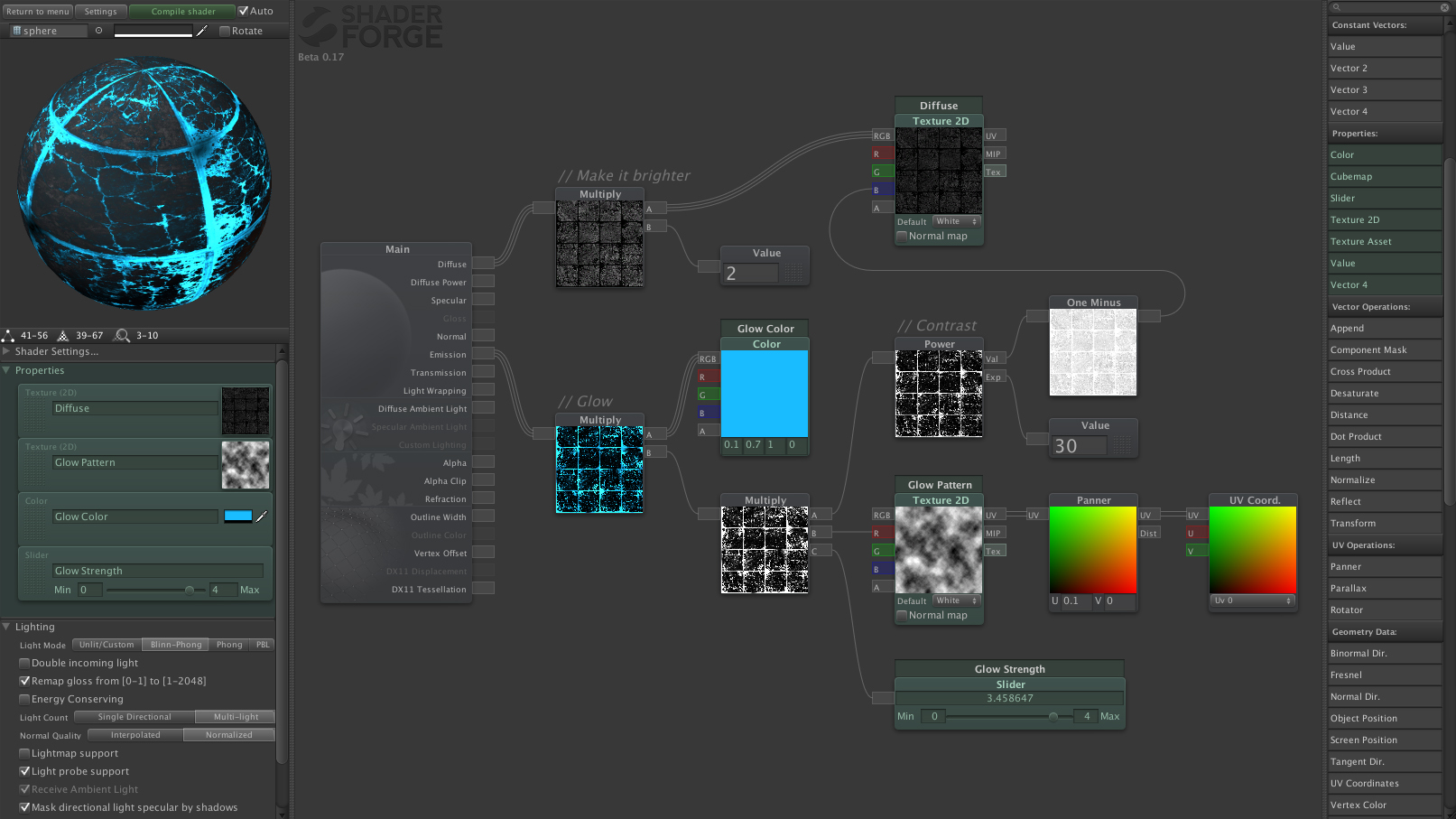
The main problem with procedural tools is the coding requirement to create them. Writing a fence generator isn’t the most trivial of tasks, let alone if you are a designer without coding experience. However in recent years, many creative tools have been using node-based interfaces to help with this barrier. Many shader editors (such as Shader Forge, Amplify, or Shader Graph) have completely eliminated the need for artists to learn how to write shader code, instead working with an intuitive graphical interface to design them.
One of the highlights of working with nodes for procedural generation has been how easy and fun it has been to experiment with ideas, and I’ve been trying to nail down the reasons why. Shader editors make a lot of sense in this regard since it’s a visual medium, and being able to preview every step along the way makes a ton of sense for the tools, but this doesn’t fully explain necessarily why I’ve been enjoying my procgen tools in the same way. There is definitely an overlap but I think another important aspect is how encapsulated the nodes are.
Every time I create a node, the natural process is to break down my idea into the simplest part; Generate a noise texture, generate a convex mesh of points, etc etc, rather than make a complex system in just a single node. This means that every node I create will be able to interact with many other immediately, and I can suddenly start plugging things together I had no intention of previously. They’re just there on the graph and its just a click and drag to connect them up! When coding these systems, these ideas never spring to mind and hooking things up together can be really difficult. This hyper-modular approach I feel is a huge benefit to creativity that is really difficult to replicate in coding.
I didn’t really have much of a conclusive point to make here, but rather my recent work has really got my mind racing about the potential of node systems. I still have a lot more ideas I want to talk about so I expect I’ll be writing more posts soon!
Thank you for reading my Post Online!
⚠️Feel free to contact me via bluesky or mastodon if you have any questions or comments!!!!
💛And please consider supporting me on patreon so I can keep making stuff!!!
Dan Fessler has some real good node thoughts in a thread here.
Here is a list of popular node based editors:
Every one of these uses a unique system for their node graphs. Some kind of standardised node-based language/system would be really nice! I’ve been using xnode in unity and really enjoying it, but it is specific to Unity rather than a generalised tool.
Node based systems are often basically functional programming? That’s pretty cool.

So I’ve been playing around with a little bitmap font shader in Unity! Let’s go over how it works???
First up I needed a font to work with, and because I love reinventing the wheel let’s go make one ourselves
When drawing a font I use an ASCII table to reference both what characters I will need, and what order they should be in to simplify figuring out the characters. If I stick to the ASCII order, then I can swap between numbers and characters with no hassle (65 == A, 66 = B, etc.)

I decided to go with 8x12 for the font, giving me enough room to comfortably work in (especially vertically, since most fonts are taller than they are wide), and set out a few little rules to help me go.
⚠️ disclaimer: i know very little about how to make fonts!!! making fonts is a Whole Thing and you should look up some cool info about that instead of me making it up as i go ⚠️

For legibility, layout and consistency I stuck to a main 5x5 section for the “body” of the letter, with a section above and beloy for any extended parts. Aside from that, I kept style consistent throughout by sticking to the same shape of curve on all the letters. It’s far from perfect but simple enough to draw out all the letters and is legible enough for what I want.
My idea for rendering this font was to draw the index of every character to a pixel in a texture, then use a shader to render the font character in place of each pixel. The texture would end up looking something like this:

So lets go about generating this texture!
After adding a quad to my scene, I started my generation script, which needs a few bits of setup:
// The input text, and the material to apply the texture to
public TextAsset textFile;
public Material material;

// How many characters to display on our texture, will literally be the dimensions of the texture
public int width;
public int height;

/*
    My favourite way of adding a cheap button to the inspector.

    When you click the `work` checkbox, it'll call the method and unset itself
    immediately; meaning you can call the function on demand instead of as part
    of Start() or on a key press etc. I use this all the time for testing and
    prototyping
*/
public bool work = false;
void Update()
{
    // Fake button
    if (work) {
        work = false;
        Work();
    }
}

void Work()
{
    print("Hello!");
}

And now we can get to work on the actual stuff!
void Work() {
    Texture2D texture = new Texture(width, height);

    // When working with textures as data rather than images as we are, it is super
    // important to turn off texture filtering, or we'll get some messed up images.
    // I'll put some examples of such at the end of the post for fun
    texture.filterMode = FilterMode.Point;

    // We will be calculating the x, y coordinate of each character instead of
    // iterating over every pixel of the texture
    int x = 0;
    int y = height - 1; // We want to start at the top of the texture, not the bottom
    for (int i = 0; i < text.Length; i++) {
        if (text[i] == 10) { // Newline character
            x = 0;
            y -= 1; // Move to the start of a new line
        } else {
            texture.SetPixel32(
                x, y,

                // Color32 uses bytes instead of floats for each channel, which makes
                // more sense for us since we're reading "bytes" from the text itself
                new Color32(
                    (byte)text[i],
                    0,
                    0,
                    0
                )
            );

            x += 1;
        }

        // It is faster to use SetPixels32() instead of setting each pixel individually!
        // I am only using SetPixel32() here for ease of explanation, and since it
        // shouldn't be *too* slow since we don't need to do it a lot anyway.

        // You will also want to make sure you aren't writing outside the bounds of the texture!
        // Again, I left this out for brevity/clarity.
    }

    // When writing to a texture you gotta remember to tell unity you updated it!
    texture.Apply();

    material.SetTexture("_MainTex", texture);
}
And this gets us our Cool greyscale image from before. Now lets move on to the shader itself. I started out with the default Unlit shader in unity (R-click > Create > Shader > Unlit Shader) and head to the frag() function.
// This is a Unity-provided property which defines the texture dimensions of an input texture
// _MainTex_TexelSize.xy is the width and height of the texture in pixels
// This lets use define one character == one pixel
float4 _MainTex_TexelSize;

fixed4 frag (v2f i) : SV_Target
{
    // The first thing we need to do is get a UV coords for each character,
    // so we can render a character correctly.

    // wrap the input UV by the texture size in pixels
    float2 charUV = (i.uv / _MainTex_TexelSize.xy) % 1.0;

    // Let's look at it to confirm it's working correctly
    return float4(charUV,0,1);
}
 Now we have a 0-1 UV space for where each character should be
However, since each character is only a small part of the font texture, we need to shrink it down some:
fixed4 frag (v2f i) : SV_Target
{
    float2 charUV = (i.uv / _MainTex_TexelSize.xy) % 1.0;
    // Resize the UV based on the font dimensions
    // There are 16 characters across, and 8 characters down
    charUV /= float2(16,8);
}
Now we can work on rendering the font itself:
fixed4 frag (v2f i) : SV_Target
{
    // Individual character UV
    float2 charUV = (i.uv / _MainTex_TexelSize.xy) % 1.0;
    charUV /= float2(16,8);

    // We can extract the character index from the red channel like this
    // The value returned will be in the range 0-1 so we need to expand
    // it to 0-256 for convenience
    fixed4 col = tex2D(_MainTex, i.uv);
    float character = col.r * 256;

    // Since our font texture is 16 characters wide by 8 characters tall,
    // we need to extract the x, y coordinate of the character on the texture
    float2 charIndexUV = float2 (
        floor(character % 16),
        floor(character / 16)
    );

    // Now we map the value back down to the 0-1 range to look it up on the texture
    charIndexUV.x /= 16.0;
    charIndexUV.y /= 8.0;

    // Lets take a look at what's happening
    return float4(charIndexUV,0,1);
}

The red and green colors here should match up with the position of the character on our font sheet! But clearly we can’t necessarily confirm that haha. Lets get fonts on screen
fixed4 frag (v2f i) : SV_Target
{
    // Individual character UV
    float2 charUV = (i.uv / _MainTex_TexelSize.xy) % 1.0;
    charUV /= float2(16,8);

    // Character index UV
    fixed4 col = tex2D(_MainTex, i.uv);
    float character = col.r * 256;

    float2 charIndexUV = float2 (
        floor(character % 16),
        floor(character / 16)
    );

    charIndexUV.x /= 16.0;
    charIndexUV.y /= 8.0;

    // Font render
    float4 fontRead = tex2D(_Font, charIndexUV + charUV);
    return fontRead;
}

Hooray! It works, first time!!!
Ok so we can at least confirm that each character is rendering correctly, so the UV space calculations all work correctly there, but clearly the offset are wrong for the character index.
It turns out the problem (after a lot of trial and error), was that it was reading the characters from the bottom up, instead of top down like I assumed. This is the line that fixes it:
charIndexUV.y = 7 - charIndexUV.y;

Congratulations friends we made a text rending shader! With mine I tried a few things out with it, the main being storing color and animation info in the remaining channels (remember we are only using the Red channel currently!) which allowed me to create the funky gifs with syntax highlighting etc. There are tons of other possibilities tho! Go make something very cool!
I also wrote a little bit of formatting syntax so I could write text files with highlighting and timing (used for the gif at the top). The script itself is below.
Thanks for reading!!
⚠️Feel free to contact me via bluesky or mastodon if you have any questions or comments!!!! And please consider supporting me on patreon so I can keep making stuff like this!!!
Bilinear filtering on the text texture:

Script used for the first gif
$S5Bootup sequence
[$S2...............$S3.....$S1...........] $S8$C7OK!
$S1
$S5$C4/!\ $C0 WELCOME TO JAZZ OS $C4/!\
$S1
$S5
Detecting input devices$S3.....
$S4$C0Keyboard:$S1 $S8$C7OK!
$S4$C0Mouse:$S1 $S8$C7OK!
$S4$C0VR Device:$S1 $S8$C2Not Found!$S1    $S5$C0but that's ok
$S1
$C5Z$C1o$C2w$C3e$C4e $C5W$C6o$C7w$C8e$C4e$C5!
$S[1-9] Set the speed of the text, higher is faster
$C[0-9] Set the color of the following text
Bilinear Filtering on just the charIndexUV:


I’ve been thinking a lot about bits and bytes, and really low level compression of data. In a beautifully compressed epiphany last night I came up with an ingenious way of compressing 16 pixels into the space of a single color. Here’s how my adventure went.
In your average texture, each pixel has 4 bytes: Red, Green, Blue and Alpha. Normally when rendering a texture you just read the color and output that:
float4 col = tex2D(_MainTex, i.uv);
return col;
However, let’s take a look at these numbers more closely. If we lay out the bits of each channel we can start playing around with how we treat these colors.
Color(
  Red   - 0 0 0 0 0 0 0 0
  Green - 0 0 0 0 0 0 0 0
  Blue  - 0 0 0 0 0 0 0 0
  Alpha - 0 0 0 0 0 0 0 0
)
Each bit (or 0) here is just On or Off. Using binary, these rows of bits can represent every whole number from 0 to 255, which is our standard color spectrum for pixels on a screen.
I want to take these to pieces and see what else we can do with these, for instance if we just take each bit as black or white, 1 1 0 1 0 1 0 0 would become 
I took this one step further and brought in the green byte too. Using 4 bits as a row of 4 pixels, you can create a 4 x 4 grid of pixels with just two bytes:
|
|
The next step is to add colors to this, instead of using black and white. All we need to do is somehow fit red, green, and blue values for both colors into the space of. two channels???? ok fine
Here’s the layout I went with:
Blue   - R R R G G G B B
Alpha  - R R R G G G B B
What this means is i’m taking 3 bits from each channel, and using that to represent a binary number for the red value. so 0 0 1 becomes 1, 1 1 1 becomes 7 etc. Since you can’t split up 8 evenly into 3 parts, I (arbitrarily) decided to use fewer bits for blue.
If your first thought is “that’s not a lot of color depth” then… yes you’re right its terrible. To give you an idea of how much color is lost; here’s a color spectrum compresed to this new depth:

But hey who cares, we’re having fun right
Writing a shader to decompress these images turned out not to be so bad, since hlsl has bitwise operations (the common tools used for playing with bits like I am here).
The first thing to do is separate the channels out into numbers from 0-255, pretending to be a byte.
int red = col.r * 255.0;
int green = col.g * 255.0;
int blue = col.b * 255.0;
int alpha = col.a * 255.0;
Write up some helper functions for reading bits from a byte
bool getBit(int byte, int bit) {
    return (byte >> bit) & 1 ? true : false;
}

float get2Bit(int byte, int offset) {
    return (byte >> offset) & 3;
}

float get3Bit(int byte, int offset) {
    return (byte >> offset) & 7;
}

float3 getColor(int byte) {
    return float3(
        get3Bit(byte, 5) / 8.0,
        get3Bit(byte, 2) / 8.0,
        get2Bit(byte, 0) / 4.0
    );
}
and the logic for reading the correct bit for the x/y position:
i.uv *= _MainTex_TexelSize.zw * 1; // we need to use the input texture size, to space the pixels correctly
i.uv = floor(i.uv * 4) % 4; // multiply the UV so we're looking at which pixel in the 4x4 grid

float colorLerp;
if (i.uv.y < 2) {  // if we're on the top half we need to read from the Red channel
    int a = i.uv.x + (i.uv.y * 4);
    colorLerp = getBit(red, a);
} else { // otherwise, read from the Green channel
    int a = i.uv.x + ((i.uv.y-2) * 4);
    colorLerp = getBit(green, a);
}
But hey, we don’t have any pictures to play with! At first I was semi-manually building little test images to work with, but that’s no fun, so we need some way of compressing images into this new format.
Masking out the 4x4 block of pixels isn’t too difficult, I just check if each pixel is more or less than 50% bright (by adding up the red/green/blue channels individually) like so:
int pattern1Byte = 0;
int pattern2Byte = 0;
for (int i = 0; i < 8; i++) {
    float avg = (pixels[i].r + pixels[i].g + pixels[i].b) / 3f; // get the average color for the pixel we're looking at
    if (avg > 0.5) {
        pattern1Byte += 1 << i; // use cool clever bitwise logic to set the correct byte
    }

    avg = (pixels[i+8].r + pixels[i+8].g + pixels[i+8].b) / 3f; // do the same thing for the green channel
    if (avg > 0.5) {
        pattern2Byte += 1 << i;
    }
}
(disclaimer; i later on created a threshold by taking the average brightness of all the pixels first, which has much better results)
For each 4x4 block of pixels, I need to get 2 different colors to store. The way I decided to approach this was to take the threshold we defined earlier, and then average out all the colors found in each region:

Now we can compress any arbitrary image, and output it through our new shader!
top: original (512x256), middle: compressed, bottom: raw compressed data (126x64)

We successfully managed to compress and image to a sixteenth of it’s original size, which is a pretty hefty compression, but we lose a ton of color depth in the process. The range of colors we end up with is 8 reds * 8 greens * 4 blues, which is 256 colors; which could maybe be part of a pretty decent palette (see Doom or Quake for instance). Utilising this limitation means you could end up with zero color depth loss.
The biggest problem aside from the color depth loss is the shader itself; having to decompress each pixel means the GPU will be doing a ton more work compared to just pushing pixels to the screen. I’m pretty sure noone is looking for solutions to save texture memory in favor of GPU time .
It was a ton of fun to think through and implement though! Hopefully it will inspire some other cool ideas; can you think of a better way to compress 16 pixels into a single color?
For a long while I have wanted to improve my workflow when using procedurally generated content in my games, often getting tied up with implementation details rather than designing good algorithms. Recently I finally created a tool to help solve some of these issues: a custom scripting language to generate a grid of tiles, which can then be used to create objects in-game.

# basic roguelike rooms

# start from the center
Center

# build a starting room
Rect cursor 1 {3,6} {3,6}

loop {6,8}
# dig a corridor to the next room.
# this moves the cursor to the new position
Digger cursor 1 10 0.9 0.2
Rect cursor 1 {3,6} {3,6}
endloop

# outline the tiles with a wall
Expand8 1 2My intention was just to have a list of instructions that execute one after another, but after tinkering with ideas, I slowly realised what I was actually making, and it all started to seem less scary after all.
The first thing I did was to write up my basic ideas and thoughts about how it should work, both to get some advice and to think about how it would work from a higher concept level. I knew what kind of functions I wanted, and writing up this stuff helped me think about it much more clearly. This included an example script.
The idea was simple:
{a,b} with a random number between a and bloop and endloop blocks, the specified number of timesexecline function, as a simple “function” mechanismIt would run something like this:

This seemed like a simple enough concept for me to work with, but I was really unhappy with the execline function. I wanted it because I thought it would solve small code duplication problems (I could just change line 5 here and all the rooms would be consistent), but in practice it barely solved any problems, and meant I had to keep track of line numbers when *writing* the script. I wanted writing scripts to be as simple as possible.
However in practice, the idea was simple: first run through the script and find all the labels, and save what line they are at. Then, when you hit a goto, you store your current position, then jump to the label’s position. When you hit return, go back to where you last hit a goto .

The complexity I had imagined turned out to just be storing line numbers, which I already had to do with the loop function anyway. This seemed a lot simpler to tackle, and opened up a lot of potential for the scripts.
The interpreter first then needs to take the script, and split it up into lines:
string[] lines = script.Split('\n');Now I have each line of code as a separate string, in the lines array. Since I can now access each line, I can run through it like this:
int lineIndex = 0;
while (lineIndex < lines.Length) {
    // Do something with lines[lineIndex]
    lineIndex += 1;
}
Now I have it reading each line of the script individually, and I can do something with it.
A line of code in my scripting language looks something like this:
instruction arg1 arg2 arg3...
Where we have a keyword at the start to identify what the line does, and then a series of arguments to control how it does the thing. To make this easier to parse, we can once again use String.Split()
string[] thisLine = lines[lineIndex].Split(' ');
string instruction = thisLine[0];
// thisLine[1] to thisLine[whatever] are the arguments
So executing functions just means reading the instruction and calling functions depending on what it is:
if (instruction == "Rect") {
    Rect(thisLine[1], thisLine[2], thisLine[3]);
}

void Rect (string tile, string width, string height) {

}
This is roughly what my first implementation looked like; I didn’t want to deal with all the loop/return/goto things yet, just getting the basic thing working.
{a,b} random parameter. The way this works is whenever I can use a number, it could also either be the name of a variable, or the random parameter.
The first step is giving the user the ability to store variables:
Dictionary vars = new Dictionary();
if (instruction == "set") {
    vars.Add(thisLine[1], int.Parse(thisLine[2]));
}
So we now store a list of variables that the user declares. Now we need a function to take a string, and see if it is either a number, a variable, or a random parameter:
int ReadVar(string value) {    // Try and read an integer
    if (int.TryParse(value)) {
        return int.Parse(value);
    }

    // Try and read a random parameter
    if (value.Contains("{")) {
        return GetRandom(value);
    }

    // Try and read a variable
    if (vars.ContainsKey(value)) {
        return vars[value];
    }

    // Couldn't read the value!
    return -1;
}
Now we can correctly read the kind of variable, and so we can update the Rect code to look like this:
if (instruction == "Rect") {
    Rect(ReadVar(thisLine[1]),
         ReadVar(thisLine[2]),
         ReadVar(thisLine[3]));
}

void Rect(int tile, int width, int height) {

}
We have a scripting language! At this point, we can now parse and execute code, and start playing around with the scripts themselves.
My hope with this article is to dispel the idea that writing a scripting language is as daunting as it seems, just as it was for me before I tried it myself. If you have any questions, or would like more explanation about anything, please do drop me a line at bluesky or mastodon.
Thank you so much for reading! If you enjoyed this article and would like to support my work, I have a Patreon! It really helps me do more work like this. 💛

# mountain generator

set height 10

# create some peaks
loop {5,8}
setpos cursor {1,30} {1,30}
Tile cursor height
endloop

label build
set nh height
minus nh 1
Noise height nh 0.4
Expand4 height nh
minus height 1
if height == 1
end
goto build
Some ideas for expansion and little bits and pieces I missed out of the article for the sake of simplicity/conciseness:
loop function in my language works like a label read at parse time; it stores the line where it last hit a loop, and the number of loops. endloop reduces that value, and if it is greater than 0, returns to the loop point.goto, to execute different blocks of code.if and goto, is end, to end execution immediately.String.Split(). I went with the latter for simplicity, but using regex can make it much more robust. (For example, the syntax breaks if the script uses two spaces in a row)add var amount etc, instead of the typical var += amount, to make it fit the instruction args.. format. This again is very similar to how assembly works.Also, thanks to the people who helped me out with both the scripting language and writing up this post: Anotak, Joshua Skelton, Simon Howard
I’ve been working on a project over the past few weeks bringing Doom and it’s various bits and pieces into Unity, along the way attempting to write a library to let people access the data in a friendly way. It’s been a very interesting project and a fun application of the many years I’ve spent delving into the inner-workings of the game.

The first step with my project was to take the data Doom uses to store a map, and create a Mesh out of it. Simple, right?
(Note: I’m going to avoid talking about parsing the actual data, for the sake of brevity. I will possibly cover that in a future post.)
Let’s start with the walls. Walls are easy. The geometry of a wall in Doom is split into two parts: the Linedef, and the Vertexes (yeah, they aren’t called Vertices here). A linedef has a bunch of information, but the bits we care about a where it starts and ends. The vertexes, which are just (x, y) points, tell us that.

Well, that was easy. Just iterate through the Linedefs, take the start and end points, and build a vertical wall. If I want to get the texture information, I just need to get the associated Sidedefs for the lines and apply the texture. Something’s wrong here; this is going very well.
(Another note: I didn’t talk about calculating the height of walls, nor upper/lower/2sided walls; it wasn’t very interesting.)
Let’s move on, now we have the walls lets build that bit in-between them: The floors. We can take a look at the Sectors to see where to start.
Huh, ok. There doesn’t seem to be any information here on *where* the sector is, or what shape it is. I wonder if-
Oh.
So floors and ceilings in Doom kind of Don’t Exist. They’re only implied by the walls surrounding them. The engine knows where a floor is because the player is always inside one looking out. (Which makes for some interesting behaviour when you aren’t inside one)
This means that they can be absolutely any shape: They don’t need to be convex, they don’t need to be contiguous (one connected shape), they can have holes, and they don’t necessarily even need to be closed shapes. It’s very literally impossible to build a mesh of them, there aren’t enough constraints.
That didn’t stop me trying.

It turns out the only thing you need to assume is this: all sectors are closed, and if they aren’t, they probably were supposed to. It turns out all the other constraints are possible to deal with, and closing sectors automatically causes zero intended effects to break. (Within reason. There are edge cases, but let’s call them out of scope. I’m looking at you, lilith.pk3)
Triangulation is a Solved Problem. However, our specific case means that implementing a library or other method that can build a set of triangles is very difficult. There will still be a lot of steps to have organised enough information for a triangulation algorithm to deal with.
To build the sectors, I wanted to do it step by step, so I could see and evaluate my progress. To this end, if my code failed for any particular reason to build a sector, I would just move on to the next one. This way, I always had at least partial levels built; I didn’t need to get it 100% working before I could see results or try other things out.
The triangulation approach I used, which was also used for the map editor Doom Builder 2, is documented here. I worked through it step by step to solve more and more sectors that Doom threw at me.
The first step was to implement the Ear Clip algorithm, only on already contiguous and closed sectors with no holes.
The premise is rather simple. You start with some shape, and you take a point and if you can connect a line between the two neighbouring points, you can “remove” that point and call it a triangle.

This worked really well for all sectors that fit my constraints I aimed for, it took a while to write up enough of the algorithm to reach the point where I could test it, but it definitely worked really well in all the situations I expected it to.
The next step was to disconnect non-contiguous sectors. The way I approached this was to trace lines from a point in a sector, and make a list of all the lines that it touched when going from one to the next. The idea is I would be able to create a set of shapes that are completely unconnected from one another, and triangulate them separately.

When I have two separate shapes, there is a (likely) chance that one of them is actually inside the other, which indicates a hole. I knew that I could handle the situation of them being completely separated, so I first attempted to detect holes and ignore them.
For this, I needed to pick a point and ask whether it was inside a given set of lines. This confounded me for a while until I read about a surprisingly simple but effective method: the Ray casting algorithm.

If a point is within an arbitrary shape, a line from that point to somewhere you know is outside the shape (for instance +1000 in the X coordinate) will cross an odd number of lines of the shape. A point outside will cross an even number of lines (including zero).
So all I had to do was check if the points of the separate shapes were inside each other. The result of this would be one of two things: a list of shapes with nothing inside them, or a list of “shells”, which in turn contains a list of “holes”.
I could already triangulate the empty shells, which meant the next step was to move onto triangulating the shells that contained a hole. Would I need to have a new triangulation algorithm that knew how to deal with holes? There’s no way that ear clipping will know what to do when it encounters one, so it can’t really work.
It turns out the answer is don’t try and triangulate a sector with a hole: just make the sector not have any holes any more!

If you pick a point on a hole, and trace a line to somewhere on the shell, you can make a cut. The cut will then be treated as part of the shell, which connects to all the lines in the hole, which are now part of the shell too. The two points used for making the cut will be duplicated, so the ear clipping can clip them twice.
To handle multiple holes, you just need to order them and cut them sequentially; once a hole is cut, it is a valid part of the shell to cut to.
This set of processes also handles working with sectors inside holes inside other sectors, too, which I’m really glad about since trying to think about that isn’t fun.

Unfortunately, this isn’t the end. Most sectors are building really nicely at this point, but regardless of all the trouble it took me to get to this point (which I didn’t go much into, to keep this work-safe), there are a lot more situations to deal with.
Because of how the software renderer works, you can often confuse it into creating impressive visual effects. These include the Mordeth Bridge, or the Deep Water effect.

So as always, there is more to do. I would love to tackle these tricks and get them working, since they seem like a fun problem to solve. For now though, I’m going to move on from my endless triangulation nightmare and add other interesting features to my engine. I am fast approaching something that can roughly Play Doom, which is very exciting. I’ll hopefully be back soon with more!
Thank you so much for reading! You can follow me on bluesky or mastodon, you can support me through my Patreon. 💛
This post is dedicated to the memory of Kate Fox. You will not be forgotten.
Last week I decided to once again attempt to import levels from the Doom engine into Unity. There are many reasons why this interests me, from being able to use the fantastic tools available to the Doom community to help develop my games (such as Slade or Doom Builder), to using the geometry in combination with modern lighting and rendering tools.

However, as quickly as I started, my plans expanded and I had too many things I wanted to build using this as a base. I decided to split each out into a separate task and work on them individually. The first was to tackle the Software Renderer.
Doom was written back in the early 90s when graphics cards didn’t know what 3D was, and everything was drawn on the CPU. This resulted in the now infamous feat of technology that resulted in the iconic renderer used in the game. To talk about how I replicated the way it looks, I’ll first go over the steps the game uses to render a texture to the screen.

The path a pixel takes from image data to screen
Doom only uses 256 colors to render the game, each stored in the “PLAYPAL”. This is just a small file that stores a list of colors, and the rest of the game just uses indexes to refer to which color they want. (The palette can also be swapped out at runtime to create full-screen effects such as flashing yellow when you pick up an item)
The trouble with using an indexed palette is that you cannot apply transformations to the color while/before it is rendering. For instance if you wanted to create a shadow, you can’t just say “make the red color darker”. To solve this problem, iD uses a lookup table called the Colormap. This is a list of 32 mappings of palette indexes to other palette indexes, to simulate getting darker.
So to render a pixel to the screen, the engine will get the palette index of a graphic, translate it to another palette index using the Colormap and light level of the graphic, then ask the palette what color to render to the screen. This is a simple but very effective approach capable of some fantastic looking lighting.
More importantly, it can be accurately replicated with a shader.

Rendering a Doom map without the software renderer approach
To start with, I just used the palette to generate images from the texture files, which I can use with any normal shader. To make sure the Doom lighting effect was accurate I used an Unlit shader, but this approach means you can use any modern lighting approach in conjunction with the levels. There is a lot of cool potential with this, but it looks nothing like Doom.
When approaching the colormap/palette system I first considered using these textures to pick from the colormap and palette, but I realised there was a smarter approach: Instead of rendering the texture with the palette, I could just write the palette index to the Red channel, and read that value with a shader to pull colors.

Textures rendered with the palette index as the Red value
Using this, I could then create a simple shader that used the palette lookup table to render the correct color to the screen:
float indexCol = tex2D(_RenderMap, i.texcoord).r;

// add half a pixel to the index to fix interpolation issues
float4 col = tex2D(_Palette, float2(indexCol + (.5/256.0), 0.0));

return col;

Textures rendering with the palette index lookup
From here, I need to apply the brightness of the sector to the lookup, which means first passing the value to the colormap, then passing that value to the palette.
float indexCol = tex2D(_RenderMap, i.texcoord).r;

// Map a brightness value (0.0 - 1.0) to a colormap index (0 - 32)
// The colormap has 34 tables, but only the first 32 are used for lighting
float brightnessIndex = floor(_Brightness * 32.0) / 34.0;

float colormapIndex = tex2D(_Colormap, float2(indexCol + (0.5/256.0), brightnessIndex) ).r;

// add half a pixel to the index to fix interpolation issues
float4 col = tex2D(_Palette, float2(colormapIndex + (.5/256.0), 0.0) );

return col;
 Textures rendered with the sector lighting colormap lookup applied
But we aren’t quite there yet! Doom uses another simple yet effective lighting technique: textures get darker the further away they are. This is responsible for a lot of how dark and atmospheric Doom feels. For this we will need to read the depth of pixels to apply a new transformation.
My first approach was to try and use a Depth Texture, but after many hours of false starts with this approach, I found I could just used the transformed Z value of a vertex’s position to get it’s depth.
v2f vert (appdata_base v)
{
    v2f o;
    o.vertex = UnityObjectToClipPos(v.vertex);
    o.depth = o.vertex.z;
    o.texcoord = TRANSFORM_TEX(v.texcoord, _RenderMap);
    return o;
}
 Textures rendered using just their depth
Now with some tweaking of the range, I could modify the brightness value further with the depth value and get a new modified colormap index to use. I tried to use the same calculations as used by Eternity’s Cardboard renderer, to get an accurate representation. The code I referenced can be found here.
fixed4 frag (v2f i) : SV_Target
{
    float depth = saturate(1.0 - (i.depth) * 0.1);

    float li = (_Brightness * 2.0) - (224.0 / 256.0);
    li = saturate(li);
    float maxlight = (_Brightness * 2.0) - (40.0 / 256.0);
    maxlight = saturate(maxlight);
    float dscale = depth * 0.4;
    float odepth = saturate(li + dscale) + 0.01;

    float indexCol = tex2D(_RenderMap, i.texcoord).r;
    float colormapIndex = indexCol;
    float brightnessLookup = (floor((1.0-odepth) * 32.0)) / 32.0;

    float paletteIndex = tex2D(_Colormap, float2(colormapIndex + (0.5/256.0), brightnessLookup * (32.0/34.0)));

    float4 col = tex2D(_Palette, float2(paletteIndex + (.5/256.0), 0.0));

    return col;
}

The final result!
When this is stacked up side by side with the Doom engine, it is hard to tell the difference! There are still improvements to be made; I can more accurately replicate the lighting values by mapping the values correctly instead of manually tweaking it til it looks correct. However, this approach has proved to be incredibly effective, and I’m very happy with how it came out.

Comparison with Chocolate Doom
One of the cool features of using this shader is that (for the first time?) you can now view the world of Doom using a software-style renderer, and *look up and down*.
Now onto the next thing! This project has been incredibly rewarding so far, step by step building Doom from scratch in Unity. I’ve been tweeting along the way in a thread here, but I hope to share more posts like this describing in detail the techniques used for various parts of it’s development in future, including how I tackled the map triangulation. Keep an eye out for more!
Thank you for reading! You can follow me on bluesky or mastodon, and you can support me through patreon. 💛
